
Zirconia-based materials have become the premier solution for modern aerospace engineering due to their exceptional ability to withstand extreme thermal stresses, mechanical loads, and aggressive chemical environments. Picture an advanced aircraft propulsion system attempting to push past supersonic speeds. The intense thermal stress and rapid physical abrasion in these extreme aerospace environments quickly degrade conventional nickel-based superalloys, causing catastrophic cracking, rapid oxidation, and system-wide mechanical failure. To combat these destructive forces, global aerospace innovators rely on Zirconia Structural Components to insulate critical pathways, absorb extreme thermal shock, and ensure absolute operational longevity.
Why use Zirconia Structural Components in aerospace?
Aerospace engineers choose Zirconia Structural Components because they provide a rare combination of ultra-low thermal conductivity, exceptional mechanical toughness, and chemical inertness under extreme heat. These specialized elements perform reliably in environments where traditional metals would rapidly soften or oxidize. By utilizing advanced ceramic designs, you can easily protect structural elements from rapid wear and thermal fatigue during high-stress flight profiles.
What is the baddeleyite crystal structure?
Think about it. When you look closely at the atomic makeup of baddeleyite, you will discover a highly stable, ditetragonal-bipyramidal ionic network. This natural mineral structure acts as the foundational bedrock for modern engineered ceramics.
- Stable Ionic Network: The grid consists of SiO₄⁴⁻ anionic groups tightly bound with Zr⁴⁺ cations.
- Coordination Grid: Each zirconium ion is coordinated by eight oxygen ions, ensuring an incredibly strong solid-state grid.
- Chemical Insolubility: This specific layout prevents solubility and shields your components from aggressive acidic attacks.
How does polymorphism affect crystal stability?
Here is the catch: raw zirconia undergoes major structural phase changes as you heat it. If you do not control these transitions, the material will expand and crack.
The crystal structure transitions through three distinct phases:
- Monoclinic Phase: Stable at room temperature up to 1100°C, providing high density but structural vulnerability during heating.
- Tetragonal Phase: Emerges between 1100°C and 2370°C, experiencing a 3% to 5% volume contraction that must be controlled.
- Cubic Phase: Prevails from 2370°C to the extreme melting point of 2700°C, offering isotropic stability under maximum thermal loads.
What is the phase behavior of zirconia?
If you want to maintain structural integrity across these high-temperature regimes, you must understand how these phases behave under load. Controlling these transitions is the secret to engineering reliable aerospace components that will not fail during flight.
| Zirconia Phase | Temperature Range | Crystal System | Volumetric Change Risk |
|---|---|---|---|
| Monoclinic | Ambient to 1100°C | Simple Monoclinic | High risk of cracking upon heating |
| Tetragonal | 1100°C to 2370°C | Tetragonal (Ditetragonal) | Reversible 3-5% expansion upon cooling |
| Cubic | 2370°C to 2700°C | Body-Centered Cubic | Stable isotropic structure at peak heat |
Evaluating these polymorphic phases allows you to predict structural behavior and select the correct thermal profile for your application.
Key Takeaway: By understanding phase transitions, you can leverage the natural crystal stability of zirconia to prevent catastrophic thermal cracking in your critical systems.
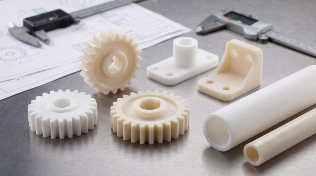
How do Zirconia Structural Components manage extreme heat?
High-performance Zirconia Structural Components manage extreme heat by utilizing localized phase transitions to dissipate thermal stresses and prevent crack propagation. This dynamic thermal management allows these parts to survive temperature spikes that would melt standard industrial alloys. By incorporating stabilized phases, you can ensure your aerospace systems operate efficiently at peak combustion temperatures.
What is phase transformation toughening?
Think about it. How does a ceramic resist cracking when subjected to sudden thermal shocks? The answer lies in its ability to actively fight crack growth at the molecular level.
- Stress Activation: The mechanical stress at a propagating crack tip triggers a spontaneous phase change.
- Phase Shift: Metastable tetragonal crystals quickly transform into the larger monoclinic phase.
- Compressive Shielding: This localized 3% to 5% volume expansion pinches the crack shut, stopping its growth.
How do stabilizing additives prevent material failure?
Here is why stabilizers are essential: they freeze the high-temperature phases in place. Without these dopants, your components would shatter during the cooling cycle.
You can utilize several key additives to achieve this stabilization:
- Yttrium Oxide (Y₂O₃): Maximizes fracture toughness and locks in the metastable tetragonal phase.
- Calcium Oxide (CaO): Provides moderate thermal shock resistance for fully stabilized cubic structures.
- Magnesium Oxide (MgO): Offers high stability in partially stabilized formulations.
How do you select the right stabilizer?
When you design aerospace hardware, matching the stabilizer to your operating environment is critical. Choosing the correct dopant ensures your parts remain stable and do not undergo unwanted phase reversion during prolonged thermal cycling.
| Stabilizing Dopant | Ionic Radius (Å) | Key Phase Stabilized | Thermal Shock Resistance |
|---|---|---|---|
| Yttrium Oxide (Y₂O₃) | 1.06 | Metastable Tetragonal (t’) | Exceptional |
| Calcium Oxide (CaO) | 1.06 | Fully Stabilized Cubic | Moderate |
| Magnesium Oxide (MgO) | 0.78 | Partially Stabilized Cubic/Tetragonal | High |
This comparison illustrates how dopant selection directly dictates the thermal and phase stability of the ceramic host lattice under extreme stress.
Key Takeaway: Selecting the correct stabilizing dopant ensures your high-temperature components maintain structural integrity throughout thousands of intense thermal cycles.
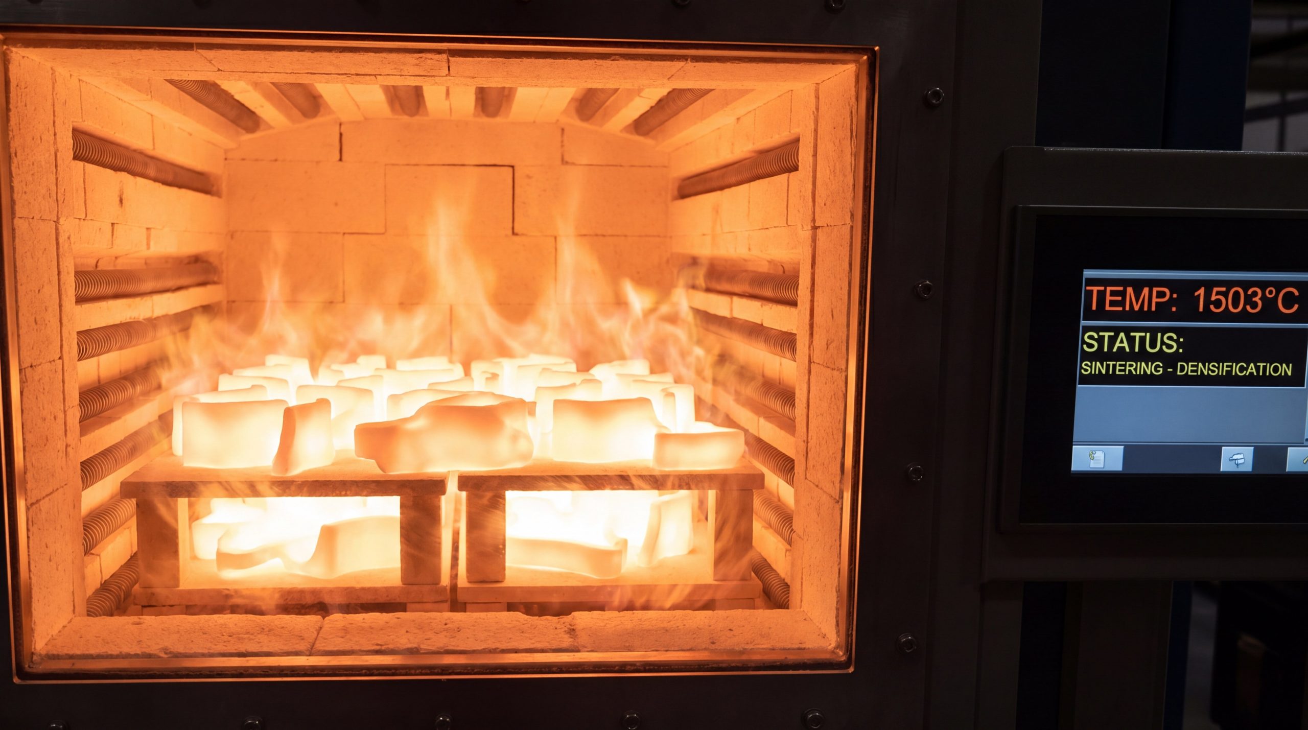
Where are Zirconia Structural Components applied in propulsion?
In modern propulsion systems, Zirconia Structural Components are primarily deployed as thermal barriers and erosion shields inside jet engines and combustion chambers. These advanced components isolate metal substrates from scorching gas flows, boosting overall turbine efficiency. By using these parts, you can confidently run engines at higher temperatures while reducing fuel burn.
Why protect jet engine turbine blades?
Look at the facts. Turbine blades face intense centrifugal forces and high-velocity exhaust gases that exceed the melting point of superalloys.
- Thermal Barrier Protection: Thin zirconia layers shield the nickel-based superalloy blades from hot gas flows.
- Creep Prevention: Lowering substrate temperatures prevents the metal from stretching or deforming over time.
- Increased Thrust: This isolation lets you safely increase combustion temperatures for maximum engine performance.
Can they line modern combustion chambers?
And the best part? Zirconia tiles make the perfect combustion chamber liners because they contain the heat where it belongs.
- Heat Retention: Insulating tiles keep heat inside the combustion zone, maximizing fuel efficiency.
- Erosion Defense: The extreme hardness of the ceramic prevents hot, high-velocity gases from eroding the chamber walls.
- Housing Protection: Thermal insulation stops localized hot spots from melting or warping the outer metallic casing.
How do they perform in hot-gas environments?
When you deploy these ceramic barriers, you can prevent structural failure across the entire exhaust assembly. These components maintain their physical shapes and protect underlying metals from rapid environmental wear.
| Engine Component | Thermal Exposure | Primary Zirconia Role | Key Failure Mechanism Prevented |
|---|---|---|---|
| Turbine Blades | 1200°C – 1600°C | Thermal Barrier Coating | Creep deformation of metal substrate |
| Combustion Liners | Up to 1700°C | Structural Insulating Tiles | Housing deformation and burn-through |
| Exhaust Nozzles | 900°C – 1300°C | Erosion-Resistant Coating | High-velocity gas-particle wear |
The data shows that custom-engineered ceramics successfully intercept heat before it can compromise structural metal backings.
Key Takeaway: Implementing zirconia-based thermal linings in your propulsion systems enables safer, more efficient flights by physically shielding critical alloy components.
What limits Zirconia Structural Components in flight?
While they are incredibly resilient, Zirconia Structural Components are limited by environmental corrosion, cyclic thermal fatigue, and hydrothermal degradation. These operational limitations require engineers to carefully design interfaces and control environmental exposures. By understanding these boundaries, you can accurately plan maintenance cycles and avoid unexpected component failures.
How does high-temperature corrosion occur?
Think about it. When an aircraft flies through dust or volcanic ash, it faces a severe threat called CMAS attack.
- Molten Glass Infiltration: Calcium-magnesium-alumino-silicates melt at high temperatures and penetrate the porous ceramic.
- Stabilizer Leaching: The molten oxides chemically dissolve the yttria stabilizer out of the zirconia lattice.
- Spallation Failure: Upon cooling, the destabilized ceramic undergoes uncontrolled phase shifts, causing the protective layer to flake off.
What is the impact of thermal fatigue?
Here is why cyclic thermal exposure is dangerous: it builds massive stresses at the material interfaces.
- Thermal Expansion Mismatch: Ceramics and metals expand at different rates, generating internal shear stress during temperature swings.
- Interfacial Microcracking: Microscopic cracks begin to form along the boundaries between the ceramic and metal bond coat.
- Coating Delamination: Over hundreds of flights, these microcracks merge, leading to complete structural separation.
How do you mitigate environmental degradation?
If you want to prevent these failure modes, you must evaluate the environmental threats and select appropriate coating thicknesses. Understanding these dynamics helps you extend component lifetime in hostile atmospheres.
| Environmental Threat | Temperature Range | Primary Driver | Microstructural Impact |
|---|---|---|---|
| CMAS Attack | Above 1200°C | Molten silicate dust penetration | Dissolution of stabilizers, phase decay |
| Thermal Fatigue | Cyclic (Ambient to 1400°C) | Mismatched thermal expansion rates | Microcrack propagation, coating flaking |
| Oxidation of Bond Coat | 900°C – 1100°C | Oxygen diffusion through ceramic | Formation of brittle thermally grown oxide |
| Hydrothermal Decay | 100°C – 300°C | Moisture exposure | Low-temperature spontaneous monoclinic shift |
This detailed mapping illustrates how chemical and thermal stresses interact to degrade ceramic components over time.
Key Takeaway: Anticipating and modeling environmental degradation allows you to design robust cooling systems that keep ceramics within safe operating limits.
How to manufacture Zirconia Structural Components?
Producing Zirconia Structural Components requires a combination of advanced powder metallurgy, high-temperature sintering, and precision additive manufacturing. To achieve near-theoretical density and eliminate structural defects, you must carefully control grain growth at the nanometric scale. By choosing the right fabrication method, you can balance production costs with the complex geometries required for aerospace parts.
Can we use additive manufacturing?
The future is here! You can now 3D print complex ceramic parts that were once impossible to machine.
- Ceramic Stereolithography (SLA): Light-cured resins mixed with zirconia powder are built layer-by-layer to form complex internal channels.
- Selective Laser Sintering (SLS): High-power lasers fuse powder mixtures directly, speeding up rapid prototyping.
- Complex Internal Cooling: This freedom allows you to design intricate internal passages that keep components cool under stress.
What is the role of sintering and powder prep?
Why does this matter? Sintering is the critical step that turns fragile green bodies into ultra-hard structural parts.
- High-Heat Densification: Firing parts at 1400°C to 1600°C triggers atomic diffusion and eliminates internal voids.
- Grain Boundary Control: Restricting grain growth ensures high mechanical toughness and prevents microstructural defects.
- Hot Isostatic Pressing (HIP): Combining heat and high pressure squeezes out remaining pores to reach maximum density.
Which manufacturing pathway fits your project?
When you evaluate manufacturing options, you must balance dimensional accuracy against production volume and raw tooling costs. Finding the right process ensures your parts meet exact aerospace tolerances.
| Fabrication Method | Dimensional Precision | Geometrical Complexity | Target Density Achieved |
|---|---|---|---|
| SLA 3D Printing | High (± 0.05 mm) | Extremely High | 97% – 99% after sintering |
| Isostatic Pressing | Moderate (Requires Machining) | Low to Medium | 99.5% – 99.9% (With HIP) |
| Slip Casting | Low to Moderate | Medium | 95% – 98% |
This manufacturing breakdown guides you in selecting the ideal production route based on structural requirements and geometry.
Key Takeaway: Choosing the optimal consolidation technique like SLA printing or HIP ensures your custom ceramic parts deliver flawless, defect-free service under load.
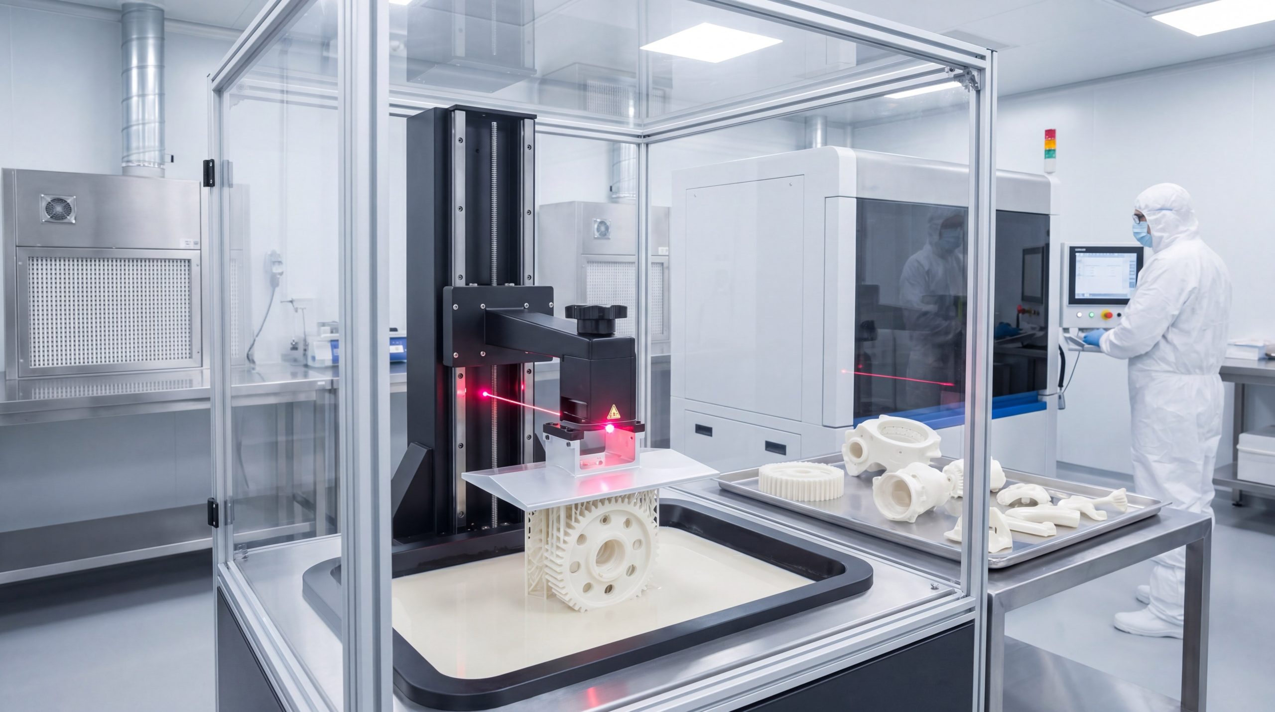
Why trust Zirconia Structural Components under load?
Modern aerospace engineers trust Zirconia Structural Components under load because they provide exceptional flexural strength, superior hardness, and unmatched creep resistance compared to metals. These ceramics do not undergo plastic deformation, ensuring that rotating parts maintain their exact tolerances during high-G maneuvers. By choosing these parts, you can confidently build high-load assemblies that endure intense mechanical stress.
How do they handle intense physical stress?
Here is the proof: zirconia ceramics display mechanical properties that rival some structural metals.
- Flexural Strength: Capable of withstanding bending stresses up to 1000 MPa, easily outperforming alumina.
- Compressive Limits: Showing compressive limits exceeding 2000 MPa, making them ideal for heavy structural joints.
- Vickers Hardness: Achieving hardness levels up to 1200 HV to prevent surface wear and scratching.
Is high-temperature creep resistance superior?
Think about it. While metal superalloys soften and begin to stretch under high heat, zirconia remains perfectly rigid.
- Stiffness Retention: Maintains high elastic modulus even when exposed to temperatures above 1000°C.
- Zero Plastic Deformation: Resists slow, heat-induced stretching (creep) under continuous mechanical loads.
- Tight Tolerances: Ensures rotating engine parts do not expand and rub against housing walls during flight.
How does zirconia compare to superalloys?
When you compare advanced ceramics to traditional aerospace metals, the weight and thermal benefits become obvious. Substituting heavy superalloys with lightweight ceramics directly translates to lighter aircraft and lower emissions.
| Material Property | Yttria-Stabilized Zirconia (YSZ) | Nickel Superalloy (Inconel 718) | Design Advantage |
|---|---|---|---|
| Density (g/cm³) | ~6.0 | ~8.2 | 26% weight reduction |
| Vickers Hardness (HV) | 1200 | 400 | Superior wear and erosion life |
| Melting Point (°C) | ~2700 | ~1300 | Operates in extreme thermal zones |
| Thermal Conductivity (W/m·K) | 2.0 – 2.5 | 11.4 | Provides high thermal insulation |
The physical data highlights how advanced ceramics easily outperform high-performance metals in wear, density, and thermal defense.
Key Takeaway: Replacing heavy superalloy parts with high-strength zirconia ceramics reduces system weight by over 25% while dramatically raising operational heat limits.
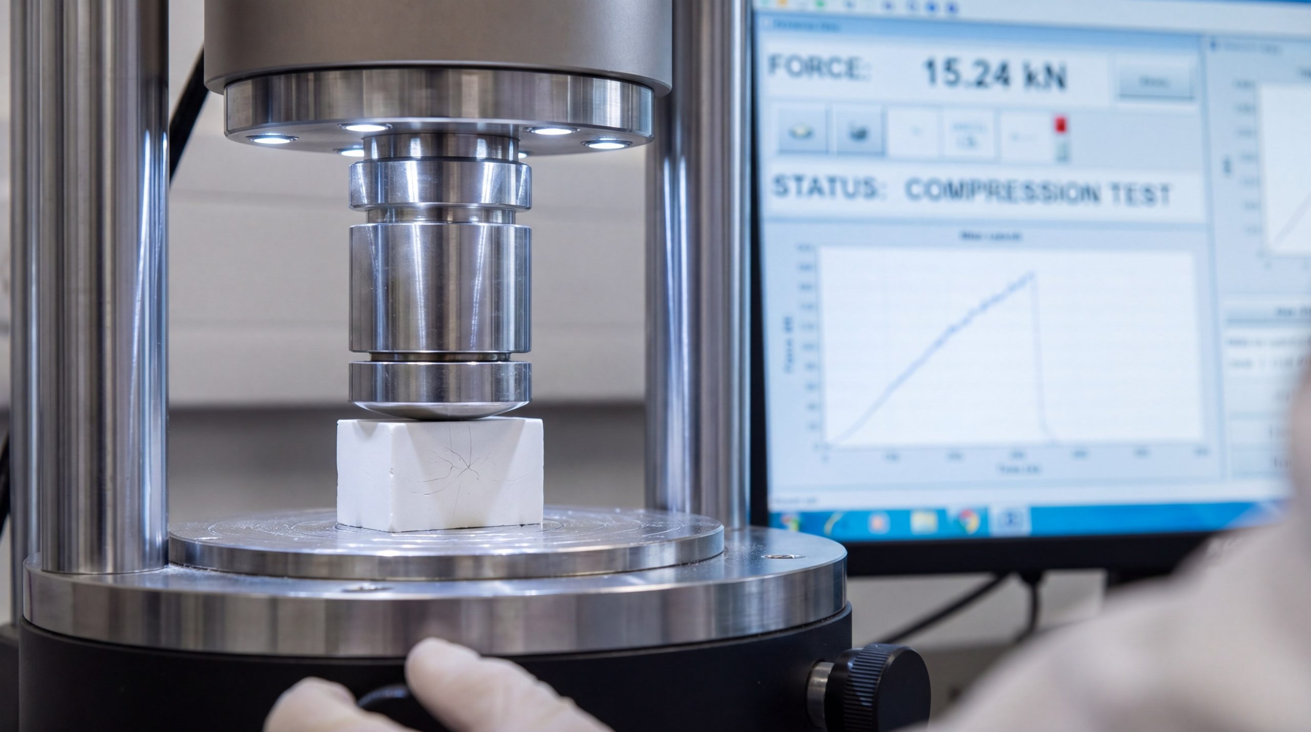
Can Zirconia Structural Components block thermal transfer?
Yes, Zirconia Structural Components act as outstanding thermal barriers due to their low intrinsic thermal conductivity and high coefficients of thermal expansion that match metallic substrates. These unique characteristics prevent high heat from penetrating critical aircraft structures and engine backings. By deploying these parts, you can insulate sensitive control lines and keep internal temperatures within safe, manageable ranges.
How do coatings insulate superalloys?
This is crucial. Thermal barrier coatings (TBCs) act as a solid heat shield, creating a major temperature drop across the ceramic layer.
- Heat Blockade: Low thermal conductivity (2.0 to 2.5 W/m·K) slows down heat transfer into underlying parts.
- Expansion Matching: A high thermal expansion rate (~10 x 10⁻⁶/K) keeps the ceramic from cracking off the expanding metal substrate.
- Substrate Temperature Drop: Lowers the metal backing temperature by 100°C to 300°C to prolong alloy life.
What is the best deposition method?
The choice is clear. Depending on your component’s job, you can choose from three main coating techniques.
- Atmospheric Plasma Spraying (APS): Deposits thick, porous layers that offer superior insulation and thermal shock resistance.
- Electron Beam Physical Vapor Deposition (EB-PVD): Creates a columnar, strain-tolerant microstructure that resists thermal expansion shear.
- High-Velocity Oxy-Fuel (HVOF): Produces ultra-dense, wear-resistant coatings ideal for fast-flowing abrasive streams.
Which coating microstructure fits your design?
When you evaluate coating deposition, you must choose between maximum thermal insulation and maximum mechanical strain tolerance. Understanding these microstructural options helps you optimize coating life in aggressive gas paths.
| Deposition Method | Microstructure Type | Key Advantage | Typical Coating Thickness |
|---|---|---|---|
| APS (Plasma Spray) | Lamellar with splats/porosity | Lowest thermal conductivity | 250 – 500 microns |
| EB-PVD | Columnar crystals | Superior strain tolerance | 100 – 250 microns |
| HVOF | Highly dense/layered | Excellent erosion resistance | 150 – 300 microns |
This coating overview illustrates how different deposition techniques directly shape the ceramic’s microstructural layout and thickness.
Key Takeaway: Selecting the proper coating deposition method like EB-PVD or APS allows you to tailor the ceramic’s thermal shielding to match your exact exhaust environment.
How tough are Zirconia Structural Components in stress?
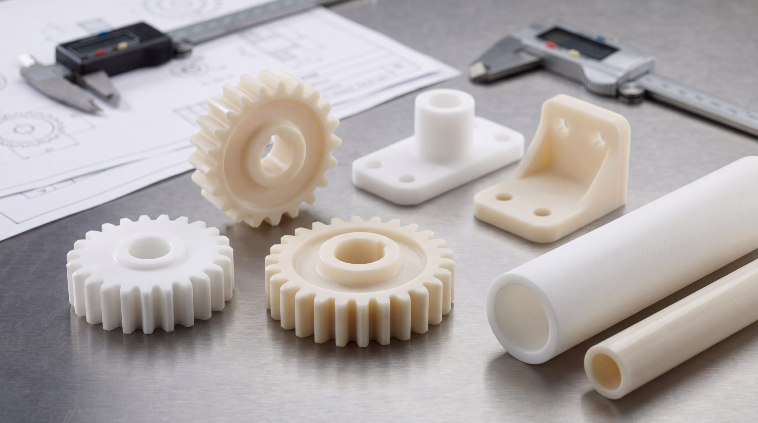
Highly optimized Zirconia Structural Components exhibit incredible mechanical toughness because they utilize controlled stabilizer levels to prevent brittle fracture. This unique atomic formulation turns brittle zirconia into “ceramic steel,” a material capable of stopping cracks in their tracks. By choosing the correct grade, you can ensure your components survive high mechanical shock and intense vibrational stress in flight.
What is the difference between PSZ and TZP?
Let’s break it down. While both materials are incredibly tough, they rely on different microstructures to survive stress.
- Partially Stabilized Zirconia (PSZ): Consists of a cubic matrix embedded with fine, coherent tetragonal precipitates.
- Tetragonal Zirconia Polycrystal (TZP): Composed of 100% fine, metastable tetragonal grains for maximum mechanical strength.
- Toughening Efficiency: TZP displays the highest room-temperature strength, while PSZ performs better at extreme temperatures.
Why is 7YSZ the optimal aerospace standard?
Think about this. Why does the aerospace industry rely so heavily on 7 wt% Yttria-Stabilized Zirconia (7YSZ)?
- Optimal Toughness: 7YSZ balances stabilizer levels to maximize fracture toughness at 3.0 MPa·m^0.5.
- Metastable Phase Balance: Keeps the tetragonal prime phase stable, preventing spontaneous degradation during thermal cycles.
- Phase Shift Capability: Retains enough transformable phase to activate the crack-pinning mechanism when stressed.
How does stabilizer content affect toughness?
When you specify stabilizer levels, you must find the perfect balance between phase stability and mechanical toughness. Fully stabilizing the material eliminates the phase shift, which actually reduces its crack-resisting power.
| Zirconia Grade | Dopant Level | Microstructure Type | Fracture Toughness (MPa·m^0.5) |
|---|---|---|---|
| 7YSZ (TBC Standard) | 7 – 8 wt% Y₂O₃ | Metastable Tetragonal (t’) | 3.0 |
| 20YSZ (Fully Stabilized) | 20 wt% Y₂O₃ | Stable Cubic | 1.0 – 1.2 |
| Mg-PSZ | 8 – 10 wt% MgO | Cubic with Tetragonal precipitates | 5.0 – 8.0 |
This toughness comparison demonstrates why precise dopant control is critical for maximizing mechanical reliability under stress.
Key Takeaway: Specifying 7YSZ or Mg-PSZ ensures your parts utilize the phase transformation toughening mechanism to actively stop cracks from spreading.
Who needs Zirconia Structural Components in defense?
Defense contractors, spacecraft designers, and high-performance instrument manufacturers require Zirconia Structural Components to survive extreme hypersonic speeds and atmospheric reentry. These specialized parts protect sensitive control surfaces and internal payloads from high friction and plasma heat. By implementing these advanced ceramic systems, you can ensure your defense hardware operates flawlessly under extreme thermal loads.
How do they protect space reentry vehicles?
In extreme scenarios, spacecraft hulls face scorching temperatures exceeding 1600°C as they plunge back to Earth.
- Reentry Shielding: Zirconia ceramic tiles act as a solid defense line, keeping the inner aluminum hull cool.
- Ablation Resistance: The ceramic’s high stability prevents hot-gas erosion from wearing down leading aerodynamic edges.
- Shape Retention: Maintaining nose cone geometry ensures your vehicle remains aerodynamically stable during descent.
Can they operate as high-performance sensors?
The exciting part? Zirconia’s electrical properties make it perfect for real-time monitoring in harsh engine zones.
- Oxygen Sensors: Under high heat, zirconia conducts oxygen ions, letting you monitor combustion efficiency in real time.
- Pressure Monitors: High stiffness and strength shield piezo components, ensuring precise pressure readings in loud engines.
- Protection Tubes: Gas-tight ceramic tubes protect sensitive temperature probes from corrosive combustion gases.
Where are these ceramics deployed in defense?
When you deploy these ceramics across aerospace and defense architectures, you gain an unmatched thermal and mechanical advantage. These parts ensure that critical guidance systems, sensors, and structural frames survive the harshest environments.
| Aerospace Sector | Targeted Application | Operating Stress | Engineered Zirconia Solution |
|---|---|---|---|
| Space Vehicles | Reentry hull shielding | Ablative heat & plasma flow | Thermal protection system tiles |
| Hypersonics | Control fins & nose cones | Aerodynamic friction & shear | Ultra-high temperature ceramics |
| Engine Sensors | Oxygen & pressure monitors | Aggressive chemical corrosion | Dense, gas-tight sensor housings |
This tactical mapping shows how zirconia’s multi-functional properties solve complex engineering challenges across multiple defense platforms.
Key Takeaway: Utilizing advanced zirconia shields in your defense designs protects sensitive electronics and structures from extreme hypersonic friction and heat.
What is next for Zirconia Structural Components?
The next generation of Zirconia Structural Components will focus on smart, multi-element doped, and digital-ready designs produced via advanced 3D printing. These emerging developments aim to reduce finishing costs and improve hydrothermal stability in moist environments. By staying ahead of these trends, you can easily design smarter, lighter, and more durable aerospace systems.
What are the remaining processing challenges?
We must face this: producing and finishing high-strength ceramics remains a complex and expensive process.
- High Tooling Costs: The exceptional hardness of sintered parts requires slow, expensive diamond-tipped grinding.
- Hydrothermal Degradation: Low-temperature moisture (100°C to 300°C) can trigger unwanted phase shifts over time.
- Powder Purity: Sourcing ultra-pure raw materials is a highly chemical-intensive and expensive process.
How will digital technologies reshape production?
Look ahead! Sintering simulations and advanced printing technologies are quickly overcoming traditional processing bottlenecks.
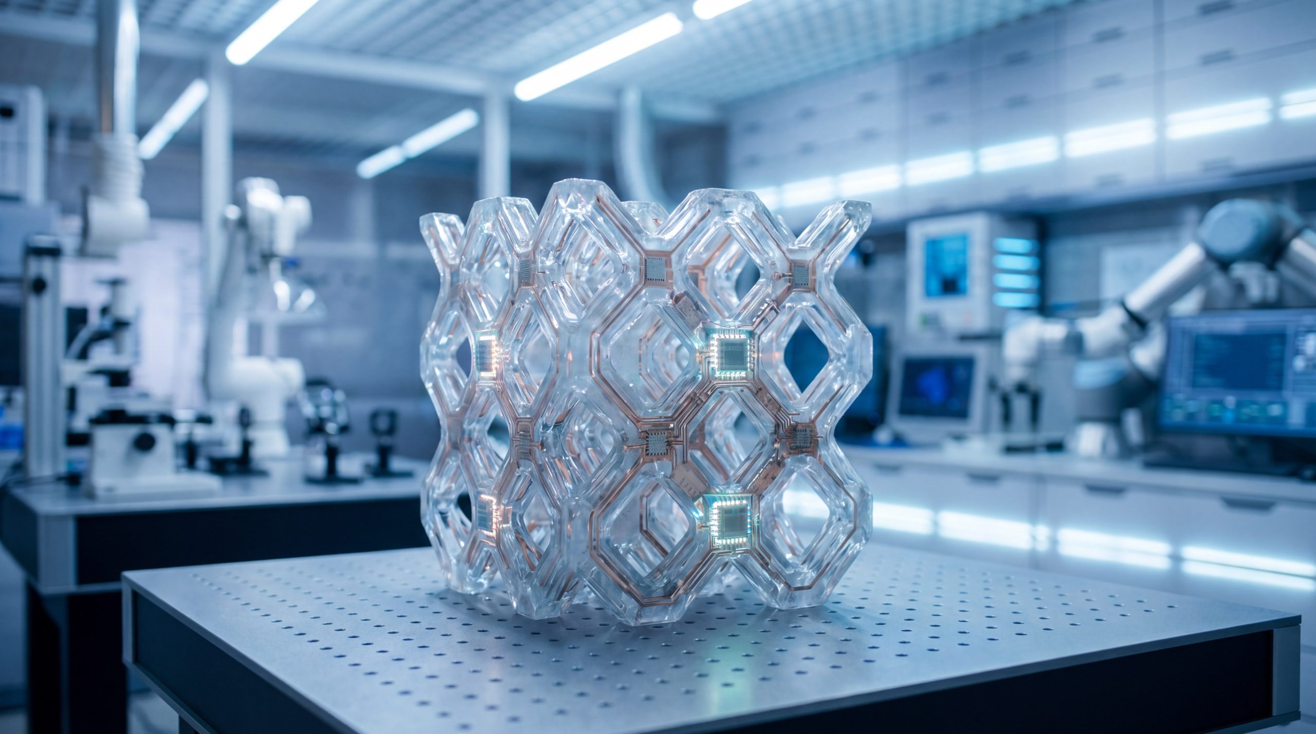
- Embedded Smart Sensors: Engineers are printing sensors directly inside zirconia parts to monitor stress in real time.
- Multi-Element Co-Doping: Adding rare-earth oxides helps achieve exceptionally low thermal conductivity levels.
- Digital Twin Firing: Computer simulations predict exact kiln shrinkage, eliminating internal stresses and micro-voids.
What is the development timeline for smart ceramics?
When you look at the research pipeline, you can expect major breakthroughs in stability and smart integration over the next few years. These innovations will open up exciting new possibilities for aerospace design.
| Future Focus Area | Core Objective | Enabling Technology | Expected Timeline |
|---|---|---|---|
| Cost Reduction | Lower final machining costs | Net-shape additive manufacturing | 2 – 4 Years |
| Hydrothermal Stability | Prevent low-temperature decay | Alumina-doping & grain boundary control | 1 – 3 Years |
| Multifunctional Ceramic | Integrated sensing & shielding | Embedded electronics in 3D-printed parts | 5+ Years |
This development roadmap outlines the key technical milestones that will drive the future of advanced ceramics.
Key Takeaway: Preparing your designs for smart, 3D-printed ceramics lets you leapfrog traditional thermal limits and build self-monitoring aerospace platforms.
Conclusion
Zirconia-based materials represent the definitive answer to the thermal and mechanical limitations that slow down modern aerospace development. By utilizing transformation-toughened microstructures, custom stabilizer formulations, and precision additive manufacturing, you can design parts that confidently push past conventional alloy performance limits. Whether applied as insulating combustion liners, stress-tolerant turbine coatings, or high-performance exhaust sensors, these advanced ceramics guarantee physical integrity under the most grueling flight conditions. To optimize your thermal protection and structural stability in extreme environments, contact us today to collaborate with our application engineering specialists on custom-engineered ceramic solutions.
Frequently Asked Questions
Can I customize Zirconia Structural Components for specific engine geometries?
Yes, absolutely. You can custom-tailor these components using advanced precision methods like stereolithography (SLA 3D printing) and diamond machining to fit complex cooling channels, thin-walled designs, and intricate aerodynamic geometries.
What’s the best stabilizer for high-temperature thermal cycling?
Yttrium oxide (Y₂O₃) is the premier option. At concentrations of 7 to 8 weight percent (known as 7YSZ), it stabilizes the highly strain-tolerant metastable tetragonal phase to resist sudden thermal shock and prevent catastrophic peeling.
How do I know if my design requires PSZ or TZP?
It depends on your operating temperature and stress profile. Tetragonal Zirconia Polycrystal (TZP) provides maximum mechanical toughness and strength at lower to moderate heats, whereas Partially Stabilized Zirconia (PSZ) offers superior long-term stability and creep resistance in extreme heat.
Can zirconia coatings be applied to old superalloy parts?
Yes, they certainly can. By applying a metallic bond coat first to guarantee optimal adhesion and prevent oxidation, you can deposit high-performance zirconia coatings onto older superalloy engine components using plasma spraying.